CANopen over EtherCAT for electrical drives
CANopen also defines several device profiles by establishing standard behavior and communication objects for similar devices. In the case of electrical drives, the profile is given by the CiA402 (“CANopen device profile for drives and motion control”) norm compliant with the IEC standard that defines programming languages for programmable control systems. The CiA402 norm specifies specific objects in OD in range 0x6000 to 0x67fe, what guarantees, that for a drive compatible with CiA402, typical process values such as position, velocity, or torque set-points and actual values will always be defined in the same objects with the same address regardless of the manufacturer and by such simplifies the commissioning of different drives. CIA402 also defines a state machine that corresponds to the drive’s actual operating state (Disabled, Fault, Switch ON, etc.). This state machine is controlled and monitored by two mandatory PDO entries: Control Word and Status Word. The drive cannot be started until the state machine has been put into the appropriate state.
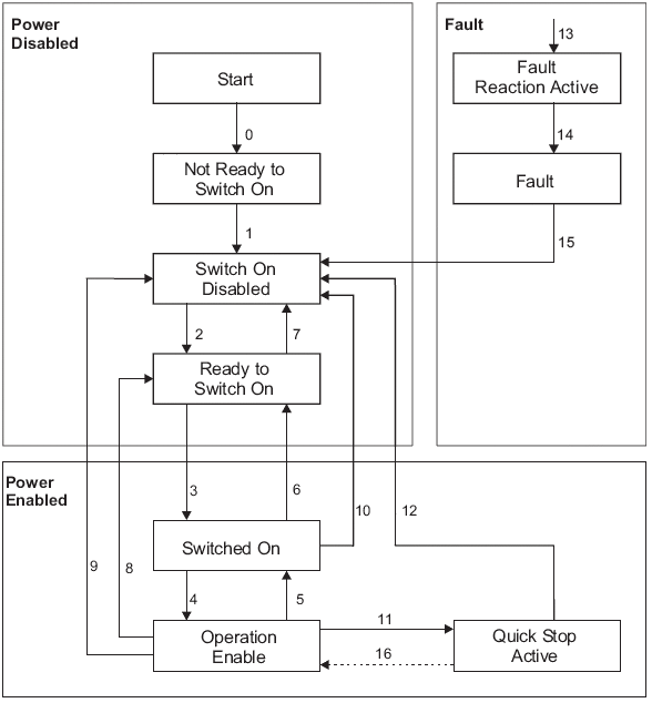
The device states and possible control sequences of the drive are described by the CANopen state machine as follows:
The possible drive states are :
State |
Description |
|---|---|
|
The drive is not ready to switch on. The drive is in boot phase. Drive motion functions are disabled. No communication established. |
|
The drive cannot be enabled via the EtherCAT interface. Drive motion functions are disabled. |
|
The drive can be enabled. Parameters can be transferred. Power may be applied. Drive motion functions are disabled. |
|
The drive is enabled but idle No fault detected. Power is enabled Drive motion functions are disabled. Parameters can be transferred. No set-points are transferred from the EtherCAT interface. |
|
Normal operation mode No fault detected. Drive motion functions and power are enabled. Power enabled. Set-points are transferred from the EtherCAT interface. |
|
The quick stop process is executed. Drive motion functions are disabled. Power is enabled. |
|
A fault has occurred, fault reaction processes are executed. |
|
A fault is active, Drive is stopped and its functions are disabled. |
State transitions are the result of events that can be either internal or triggers through the Control Word. When a command trigger for state change is received, the transition is performed before any other command is processed.
The possible transition states, their trigger events and performed actions are :
State Transition |
Event |
Action |
|---|---|---|
|
Automatic transition after power-on or reset application |
Drive device self-test and/or self initialization has to be performed |
|
Automatic transition |
Communication has to be activated |
|
Shutdown command from control device or local signal |
None |
|
Switch on command received from control device or local signal |
The high-level power has to be switched ON, if possible |
|
Enable operation command received from control device or local signal |
The drive function has to be enabled. All internal set-points cleared. |
|
Disable operation command received from control device or local signal |
The drive function has to be disabled. |
|
Shutdown command received from control device or local signal |
The high-level power has to be switched OFF, if possible. |
|
Quick stop or disable voltage command from control device or local signal |
None |
|
Shutdown command from control device or local signal |
The drive function has to be disabled. The high-level power has to be switched OFF, if possible. |
|
Disable voltage command from control device or local signal |
The drive function has to be disabled. The high-level power has to be switched OFF, if possible. |
|
Disable voltage or quick stop command from control device or local signal |
The high-level power has to be switched OFF, if possible. |
|
Quick stop command from control device or local signal |
The quick stop function has to be started. |
|
Either: - Automatic transition when the quick stop function is completed and quick stop option code is 1, 2, 3 or 4. - Disable voltage command received from control device (depends on the quick stop option code) |
The drive function has to be disabled. The high-level power has to be switched OFF, if possible. |
|
Fault signal |
The configured fault reaction function has to be executed. |
|
Automatic transition |
The drive function has to be disabled. The high-level power has to be switched OFF, if possible. |
|
Fault reset command from control device or local signal. |
A reset of the fault condition is performed if no fault exists currently on the drive device. After leaving the Fault state, the Fault reset bit in the control word has to be cleared by the control device. |
|
If the quick stop option code is 5, 6, 7, or 8, enable operation command from control device |
The drive function has to be enabled |
CANopen uses 16-bits Status Word and Control Word to monitor and control the state machine. These PDO entries have the following bit assignment :
Bit |
|
|
|---|---|---|
|
Ready to switch on |
Switch On |
|
Switched on |
Disable Voltage |
|
Operation Enabled |
Quick Stop |
|
Fault |
Enable Operation |
|
Voltage Enabled |
Operation-mode Specific |
|
Quick Stop |
Operation-mode Specific |
|
Switch On Disabled |
Operation-mode Specific |
|
Warning |
Reset Fault (only effective for faults) |
|
Manufacturer-specific (reserved) |
Pause/halt |
|
Remote (always 1) |
Reserved |
|
Target Reached |
Reserved |
|
Internal Limit Active |
Reserved |
|
Operation-mode Specific (reserved) |
Reserved |
|
Operation-mode Specific (reserved) |
Manufacturer-specific |
|
Manufacturer-specific (reserved) |
Manufacturer-specific |
|
Manufacturer-specific (reserved) |
Manufacturer-specific |
The Status Word is only updated and written by the drive in Safe-Op and Operational states. The current drive state can be decoded from the logical combination of the bits in the Status Word:
|
State |
|---|---|
|
Not ready to switch on |
|
Switch on disabled |
|
Ready to switch on |
|
Switched on |
|
Operation enabled |
|
Quick stop active |
|
Fault reaction active |
|
Fault |
The control commands allow the manipulation of the state of a drive by setting its control word. Commands are built up from the logical combination of the bits in the Control Word:
|
Command |
State Transitions |
|---|---|---|
|
Shutdown |
2, 6, 8 |
|
Switch On |
3 |
|
Switch On + Enable Operation |
3 + 4 |
|
Disable |
7, 9, 10, 12 |
|
Quick Stop |
7, 10, 11 |
|
Disable Operation |
5 |
|
Enable Operation |
4, 16 |
|
Fault Reset |
15 |